


Inventor
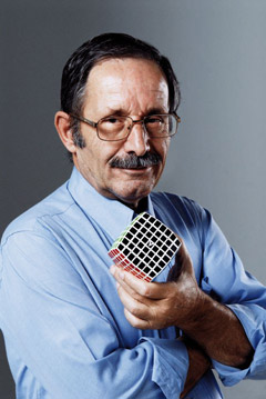 Panagiotis VERDES, an inspired Greek Surveying Engineer involved in 3D constructions and designs for over 30 years, is the inventor of V-CUBE™ technology.
Mr. VERDES was born in Chiliomodi, Korinthos, a province in southern Greece, where he graduated from high school. He followed his passion for constructions and studied at the Aristotelian University of Thessaloniki from 1965 until 1970. During his career, he was primarily involved in building, road and public network constructions until his retirement in 2003. This is when he decided to follow his “secret” passion for rotational puzzles.
Following years of innovative ideas and experiments, he created the first 6X6X6 and 7x7x7 cube worldwide! Moreover, his invention, which includes a unified rotating mechanism for any sized cube, allows the construction of smooth & sturdy cubes even reaching a size of 11X11X11 , thus invalidating a worldwide belief that the sturdy construction of cubes over 5 layers is impossible!
A brief chronicle from Inventor’s mouth:
“The whole story began in 1981, when for the first time I saw and held in my hands a 3x3x3 Cube. I felt great admiration for this astounding invention and I instantly became a fanatic fan of this puzzle. I almost immediately understood the way the cube was constructed and the way it functioned. Instantly, I thought that such a cube could be constructed with even more layers. Initially, I believed that cubes with more layers could be made, but for the sake of their structural supports, they should have only odd number of layers (N=5 or N=7, etc). I began making rough drawings and designs during my spare time, based on the use of cylindrical surfaces, following Rubik’s idea. I noticed, however, that in this sense, there was a problem in the rotation of the layers, especially for those parts which form the corner pieces of the cube. The cubes constructed thus far, including the 2X2X2 cube and in particular, the 4X4X4 & 5X5X5 cubes, had not been disengaged from the sense of using the inner cylindrical surfaces, as they are used for the construction of the Rubik’s Cube.
After many attempts and drawings, I captured the idea of using right angle conical surfaces whose axis of rotation would coincide with the semi axes of the Cartesian coordinate system. These conical surfaces specifically solved the problem of connecting the corner pieces of the cube with its inner part which was for that matter without a doubt, the vital issue. Working this particular idea meticulously with further thought, I noticed that by the use of conical surfaces in the inner part of the cube makes cubes with an even number of layers per direction to be constructed possible (i.e. cubes No 2, No 4 etc). I also noticed that by the use of conical surfaces, the number N of layers of each cube could be expressed according to the number k, (i.e. the number of cones per semi axis of the Cartesian coordinate system, with the relation: N=2k and N=2k+1). In general, the use of k number of conical surfaces per semi axis results in pairs of cubes. In any given pair, the first cube has an even number of visible layers N=2k while the second has the immediate next odd number of visible layers N=2k+1. Fundamentally, the number of the layers of this pair is exactly the same i.e. N=2k+1. This is because, in the first cube one, of the layers is not visible, and forms the middle layer of direction while on the second cube, this particular layer emerges to the surface and becomes one of the visible layers. As a result, the total number of visible layers in the second cube is N=2k+1.
This invention has been possible since the problem of connecting the corner cube piece with the solid interior has been solved, so that the said corner piece can be self-contained and rotate around any semi - axis of the three-dimensional rectangular Cartesian coordinate system, be protected during rotation by the six caps of the solid, which is the central pieces of each face, to secure that the cube is not dismantled. This solution became possible based on the following observations:
a) The diagonal of each cube with side length a forms with the semi-_axes OX, OY, OZ, of the three-dimensional rectangular Cartesian coordinate system angles equal to tanw=aΦ2/a, tanw=Φ2, therefore w=54,735610320° (figure1.1).
b) If we consider three right cones with apex to the beginning of the coordinates, said right cones having axes the positive semi - axes OX, OY, OZ, their generating line forming with the semi - axes OX, OY, OZ an angle j>w, then the intersection of these three cones is a sphenoid solid of continuously increasing thickness, said sphenoid solid’s apex being located at the beginning of the coordinates (figure 1.2), of equilateral spherical triangle cross section (figure 1.3) when cut by a spherical surface whose center coincides with the coordinates beginning. The length of the sides of the said spherical triangle increases as we approach the cube apex. The center- axis of the said sphenoid solid coincides with the diagonal of the cube.
The three side surfaces of that sphenoid solid are parts of the surfaces of the mentioned cones and, as a result, the said sphenoid solid can rotate in the internal surface of the corresponding cone, when the corresponding cone axis or the corresponding semi - axis of the three - dimensional rectangular Cartesian coordinate system rotates. Thus, if we consider that we have 1/8 of a sphere with radius R, the center of said sphere being located at the coordinates beginning, appropriately cut with planes parallel to the planes XY, YZ, ZX, as well as a small cubic piece, whose diagonal coincides with the initial cube diagonal (figure 1.4), then these three pieces (figure 1.5) embodied into a separate piece give us the general form and the general shape of the corner pieces of all the present invention cubes (figure 1.6).
It is enough, therefore, to compare the figure 1.6 with the figures 2.1, 3.1, 4.1, 5.1, 6a.1, 6b._1, 7.1, 8.1, 9.1, 10.1, 11.1, in order to decipher the unified manufactured way of the corner piece of each cube, according to the existing invention. In the above mentioned figures, one can clearly see that the three discernible parts of the corner pieces; the first part which is substantially cubic, the second part which is of a conical sphenoid shape and the third part which is a part of a sphere. Comparing the figures is enough to prove that the invention is unified and therefore produces more than one solid.
The other pieces are produced exactly the same way and their shape depends on the pieces’ location in the final solid. Their conical sphenoid part, for the configuration of which at least four conical surfaces are used, can have the same cross section all over its length or different cross-section per parts. Whatever the case, the shape of the cross-section of the said sphenoid part is either of an isosceles spherical trapezium or of any spherical quadrilateral. The configuration of this conical sphenoid part is such so as to create on each separate piece the recesses-protrusions whereby each separate piece is inter-coupled and supported by its neighboring pieces.
At the same time, the configuration of the conical sphenoid part in combination with the third lower part of the pieces creates general spherical recesses-protrusions between adjacent layers, securing the stability of the construction and guiding the layers during rotation around the axes. Finally, the lower part of the separate pieces is a piece of a sphere or of spherical shell.
All of these occurred around 1985. The general solution of constructing cubes of any size made me exceptionally happy because I realized that by the method which I described, I would be able to construct cubes of a large number of layers. All cubes constructed to date, even a 3x3x3 cube, are included but with a different internal configuration, a fact that seemed impossible and took me a long time to realize.
Some samples of the 1985’s handmade designs for the 5x5x5 cube can be seen here.
After completing my thoughts on paper through sketches, I placed them in a drawer and kept my ideas to myself. At that time I did not have internet access, or any information regarding the development of the Rubik’s Cube.
In the Fall of 2002 I visited the Rubik’s e-shop where I saw that cubes 2x2x2, 4x4x4 and 5x5x5 had been constructed, but not a 6x6x6 cube. In May of 2003, I decided to submit the drawings, which I made on my personal computer, along with the other necessary documents to the O.B.I. in Greece. One year later, I received the Greek Diploma of Invention No 1004581. Furthermore, all of the necessary documents were submitted to the WIPO/PCT as of May 2004 and to date, 51 national patents have been granted.
The solution to the present invention finds applications up to the cube N=11, as we have already mentioned, due to the increasing difficulty in solving the cubes when more layers are added, as well as the geometrical constraints and practical reasons. The geometrical constraints are as follows:
- According to the present invention, in order to divide the cube into equal N layers we have already proved that N should verify the inequality Φ2 (a/2-a/N) < a/2.Having solved the inequality, it is obvious that the whole values of N are N<6,82.This is possible when N=2, N=3, N=4, N=5 and N=6 and as a result the cubic logic toys No2, No3, No4, No5 and No6, whose shape is ideally cubic, are produced.
- The constraint in the value of N<6,82 can be overcome if the planar faces of the cube become spherical parts of long radius. Therefore, the final solid with N=7 and more layers loses the classical geometrical cubic shape, that with six planar surfaces, but from N=7 to N=11 the six solid faces are no longer planar but spherical, of long radius compared to the cube dimensions, the shape of said spherical surfaces being almost planar, as the rise of the solid faces from the ideal level, is about 5% of the side length of the ideal cube.
Although the shape of the resultant solids from N=7 to N=11 is substantially cubic, according to the Topology branch the circle and the square are exactly the same shapes and subsequently the classic cube continuously transformed to substantially cubic is the same shape as the sphere. Therefore, we think that it is reasonable to name all the solids produced by the present invention cubic logic toys No N, as they are manufactured in exactly the same unified way, that is by using conical surfaces.
The practical reasons why the present invention finds application up to the cube N=11 are the following:
a) A cube with more layers than N=11 would be hard to rotate due to its size and the large number of its separate pieces.
b) When N>10, the visible surfaces of the separate pieces that form the acmes of the cube lose their square shape and become rectangular. That’s why the invention stops at the value N=11 for which the ratio of the sides b/a of the intermediate on the acmes rectangular is1, 5.
Finally, we should mention that when N=6,the value is very close to the geometrical constraint N<6,82.As a
result, the intermediate sphenoid part of the separate pieces, especially of the corner ones, will be limited in dimensions and must be either strengthened or become bigger in size during construction. That is not the case if the cubic logic toy No 6 is manufactured in the way the cubic logic toys with N³7 are, that is with its six faces consisting of spherical parts of long radius. That’s why we suggest two different versions in manufacturing the cubic logic toy No6; version No6a is of a normal cubic shape and version No6b is with its faces consisting of spherical parts of long radius. The only difference between the two versions is in shape since they consist of exactly the same number of separate pieces.
This invention is fully understood by anyone who has a good knowledge of visual geometry. For that reason, there is an analytic description of figures from 2 to 11 accompanying the present invention and proving that:
a) The invention is a unified inventive body.
b) The invention improves the cubes manufactured, thus far in several ways and by several cube inventors, that is the 2x2x2, 4x4x4 and 5x5x5 cubes.
c) The classic 3x3x3 cube, is included in that invention with some modifications.
d) It expands for the first time worldwide, from what we know up to now, the logic toys series of substantially cubic shape up to the number No 11, i.e. the cube with 11 different layers per direction.
In any sense these are the rotational puzzles of the 21st century! "